frequency
angular frequency
Hz
rad/s
f = 1/T
ω = 2πf
P and S waves
VS
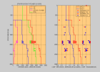
VP/VS = 1.7 in consolidated rocks
impedances
kg/m2/s
I = ρV
εxy , εyz , εzx
σxy , σyz , σzx
sinθ , 0 , cosθ
Russel D., Acoustics Animations : Longitudinal and Transverse Wave Motion
The site illustrates the 1D propagation of longitudinal and transverse harmonic waves as well as Rayleigh waves guided by a free surface.
Baker S.A. and Wysession M.E., Seismic shear wave propagation : a synthetic animation
Animations of the propagation and reflection of wave fronts in the Earth's mantle,
and examples of ray tracing and recordings.
Tanimoto T., Southern California wavefield reconstruction
Visualisation of the propagation of wave fields recorded by a dense array of seismic stations.
| . | elastic modulus | dilatation | shear | volumetric |
| strain | . | εxx = ∂ux/∂x | εxy = (∂ux/∂y+∂uy/∂x)/2 | divu = εxx+εyy+εzz |
| uniaxial compression | Young modulus E
Poisson coefficient ν | σxx = Eεxx
εyy = -νεxx | . | divu = (1-2ν)εxx |
| stress-strain relation | coef. Lamé λ , μ
bulk modulus K | σxx = λdivu+2μεxx | σxy = 2μεxy | divu = (σxx+σyy+σzz)/3K |
| relationships among moduli | E = 1010 - 1011 Pa
ν = 0.2 - 0.4 (rocks) ; 0.5 (water) | λ = Eν/((1+ν)(1-2ν)) | μ = E/(2(1+ν)) | K = λ+2μ/3 = E/(3(1-2ν)) |
Values of elastic moduli et densities for air, water and some minerals are the following :
| air | water | ice | clays | calcite CaCO3 | quartz SiO2 | olivine (Mg,Fe)SiO4 | |
| K (GPa) | 0.0001 | 2.4 | 8.4 | 25 | 70 | 37 | 130 |
| μ (GPa) | 0 | 0 | 3.6 | 9 | 29 | 44 | 80 |
| ρ (kg/m3) | 1 | 1000 | 920 | 2550 | 2700 | 2700 | 3320 |
In cylindrical coordinates (r,θ,z), the strain and stress components are :
| strain | εrr = ∂ur/∂r | εθθ = (1/r)(ur+∂uθ/∂θ) | εzz = ∂uz/∂z | εzr = (∂ur/∂z+∂uz/∂r)/2 | εrθ = ((1/r)(∂ur/∂θ-uθ)+∂uθ/∂r)/2 | εθz = ((1/r)∂uz/∂θ+∂uθ/∂z)/2 |
| stress | σrr = λdivu+2μεrr | σθθ = λdivu+2μεθθ | σzz = λdivu+2μεzz | σzr = 2μεzr | σrθ = 2μεrθ | σθz = 2μεθz |
| Compressional waves | 1D longitudinal waves | 3D acoustic waves | P waves |
| particle motion | ux(x,t) | u = gradφ(x,t) | u = gradφ(x,t) |
| strains | εxx = ∂ux/∂x | divu = Δφ | εxx = ∂2φ/∂x2 , εyy , εzz
εxy = ∂2φ/∂x∂y , εyz , εzx |
| stresses | σxx = E∂ux/∂x | p = -Kdivu | σxx = λΔφ+2μ∂2φ/∂x2 , σyy , σzz
σxy = 2μ∂2φ/∂x∂y , σyz , σzx |
| equilibrium equations | ρ∂2ux/∂t2 = ∂σxx/∂x | ρ∂2u/∂t2 = -gradp | ρ∂2ux/∂t2 = ∂σxx/∂x+∂σxy/∂y+∂σxz/∂z
ρ∂/∂x(∂2φ/∂t2) = (λ+2μ)∂/∂x(Δφ) ρgrad(∂2φ/∂t2) = (λ+2μ)grad(Δφ) |
| wave equations | ∂2ux/∂t2 = VL2∂2ux/∂x2 | ∂2p/∂t2 = VA2Δp | ∂2φ/∂t2 = VP2Δφ |
| propagation velocity | VL2 = E/ρ | VA2 = K/ρ | VP2 = (λ+2μ)/ρ |
For S waves propagating in a vertical plane (it is the case when the propagation velocity is constant or when it depends only on depth, as in a horizontally stratified medium), it is convenient to distinguish two types of transverse polarizations. SH waves have an horizontal polarization orthogonal to the propagation plane : the particle motion has a single non zero component. SV waves have a transverse polarization within the propagation plane : the two non zero components of the particle motion are obtained from a vector potential with a single non-zero component, the one that is orthogonal to the propagation plane.
| Shear waves (divu = 0) | 1D transverse wave | SH waves (polarization ⊥ propagation plane) | SV waves (polarization within the propagation plane) |
| particle motion | uy(x,t) | uy(x,z,t) | u(x,z,t) = curlψy(x,z,t)
ux = -∂ψy/∂z , uz = ∂ψy/∂x |
| strains | εxy = (1/2)∂uy/∂x | εxy = (1/2)∂uy/∂x , εyz | εxx = -∂2ψy/∂z∂x = -εzz
εxz = (-∂2ψy/∂z2+∂2ψy/∂x2)/2 |
| stresses | σxy = μ∂uy/∂x | σxy = μ∂uy/∂x , σyz | σxx = -2μ∂2ψy/∂z∂x = -σzz
σxz = μ(-∂2ψy/∂z2+∂2ψy/∂x2) |
| equilibrium equations | ρ∂2uy/∂t2 = ∂σxy/∂x | ρ∂2uy/∂t2 = ∂σxy/∂x+∂σyz/∂z | ρ∂2ux/∂t2 = ∂σxx/∂x+∂σxz/∂z
ρ∂/∂z(∂2ψy/∂t2) = μ∂/∂z(∂2ψy/∂x2+∂2ψy/∂z2) |
| wave equations | ∂2uy/∂t2 = VS2∂2uy/∂x2 | ∂2uy/∂t2 = VS2Δuy | ∂2ψy/∂t2 = VS2Δψy |
| propagation velocity | VS2 = μ/ρ | VS2 = μ/ρ | VS2 = μ/ρ |
Values of propagation velocities, Poisson coefficients and densities for some sedimentary and crystalline rocks are the following :
| unconsolidated sandstone | consolidated sandstone | limestone | granite | basalt | granulite | dunite | |
| VP (km/s) | 2.7 | 4.1 | 4.6 | 6.2 | 5.9 | 7.0 | 8.3 |
| VS (km/s) | 1.4 | 2.4 | 2.4 | 3.7 | 3.2 | 3.8 | 4.8 |
| ν = (VP2/VS2-2)/(2VP2/VS2-2) | 0.32 | 0.24 | 0.31 | 0.22 | 0.29 | 0.29 | 0.25 |
| ρ (kg/m3) | 2100 | 2400 | 2400 | 2650 | 2880 | 3000 | 3300 |
| 1D wave | P waves | S waves |
| u→ = u(x/V-t)
u← = u(-x/V-t) | φ(e.x/VP-t)
ulongitudinal = gradφ = (e/VP)φ' | ψ(e.x/VS-t)
utransverse = curlψ = (e/VS)∧ψ' |
| harmonic case : u = Ueiω(x/V-t) = Uei2π(x/λ-t/T) = Uei(kx-ωt)
u→ : k = ω/V u← : k = -ω/V | φ = Φei(k.x-ωt) , k = (ω/VP)e
u = ikΦei(k.x-ωt) | ψ = Ψei(k.x-ωt) , k = (ω/VS)e
u = ik∧Ψei(k.x-ωt) |
For harmonic waves ∂φ/∂x = ikxφ , ∂φ/∂t = -iωφ .
The wave equation becomes the dispersion relation : ω2 = (kx2+ky2+kz2)V2 .
It is a sphere of radius 1/V in the coordinates (kx/ω , ky/ω , kz/ω).
This is because in a homogeneous isotropic medium, the propagation velocity is the same in all propagation directions.
An harmonic wave fills the space with periodic oscillations.
If one looks at it or records it along its propagation direction e, one sees its true wavelength λ = 2π/k.
Along a different direction e', one sees an apparent wavelength larger than the true wavelength :
λae' = λ/cos(angle(e,e')).
Along the x,y,z axes, one sees the apparent wavelengths λx = 2π/kx , λy = 2π/ky , λz = 2π/kz.
 -
-
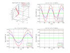 -
-
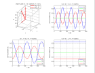 -
-
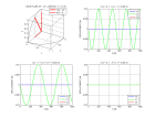
ondePS.m
| ∂2(rφ)/∂t2 = V2∂2(rφ)/∂r2 | particle motion | near/far field |
| φ = (A/r)f(±r/V-t) | u = (A/r)er(-f/r±f'/V) | . |
| φ = (A/r)ei(kr-ωt) | u = (A/r)er(ik-1/r)ei(kr-ωt) | kr>>1 u = (ikA/r)erei(kr-ωt)
kr<<1 u = (-A/r2)erei(kr-ωt) A = -U0r02 for a compressional source with radius r0<<λ |
Δφ(r) = (1/r)∂2(rφ)/∂r2 , divr = ∂x/∂x+∂y/∂y+∂z/∂z = 3 , diver = div(r/r) = grad(1/r).r+divr/r = 2/r
| . | wavefront equation | inverse of apparent velocities along axes | eikonal equation : Pythagore for waves |
| plane | T(x) = e.x/V | gradT = e/V | e.e=1
gradT.gradT = (∂T/∂x)2+(∂T/∂y)2+(∂T/∂z)2 = 1/V2 (1/Vax)2+(1/Vay)2+(1/Vaz)2 = 1/V2 |
| spherical | T(x) = r/V | gradT = er/V | |
| any surface | T(x) | gradT = eM/V |
The propagation of wavefronts obeys Huygens principle : the wavefront at time t+dt is the envelop of spherical wavelets of radii Vdt, centered on the wavefront at time t.
The geometry of rays obeys Fermat principle : the traveltime along the ray is stationary relative to any perturbation of the ray geometry.
These two principles illustrate how a wave finds its direction propagation : it tries them all and chooses those where constructive interferences occur between neighbouring paths.
They can also be numerically implemented to determine the rays geometry of the rays in nonhomogeneous media.
| Traveltime curves T(X) of direct, reflected and head waves for source-receiver offset SR=X and homogeneous media of velocity V1 and V2 | |||
| dip α | direct wave | reflected wave
total reflection for incidence θ1>θc | head wave (only if V2>V1)
critical incidence θc : sinθc = V1/V2 |

direco.m | T = X/V1 | T = (4d2+X2)½/V1 | critical distance : Xc = 2dtgθc
apparent horizontal et vertical velocities : Vax = V1/sinθc = V2 ; Vaz = V1/cosθc traveltime : T = X/Vax+2d/Vaz = X/V2+2dcosθc/V1 |

| T = X/V1 | virtual source symmetrical of the source with respect to interface
xv = 2dsinα ; zv = 2dcosα T = (4(dcosα)2+(X±2dsinα)2)½/V1
| critical distance (triangle virtual source, vertical projection of VS on surface, receiver) :
Xc = 2d(cosαtg(θc±α)-±sinα) = 2dsinθ/cos(θ±α) apparent velocities along and orthogonally to interface :
distances along and orthogonally to interface :
traveltime : T = xα/Vaα+d⊥α/Va⊥α
|
If the source-receiver direction is not parallel to the dip azimuth, the propagation occurs in the plane that is orthogonal to the interface and that includes the SR line. α is the apparent dip in the propagation plane. It is related to the true dip αtrue by the equation : sinα = sin(αtrue)cos(azimuth(RS)-azimuth(dip)).
In the elastic case, converted waves have to be taken into account. Here are the figures drawn by Cagniard in 1939 in the case where VP2>VS2>VP1>VS1 :

For a point source located on the free surface of a layer having a thickness d above a half-space, the multiple reflections between the free surface and the interface generate reverberations (see also this quiz illustrating how these reverberations give rise to guided waves).
Ocean Acoustics Library shows an animation of the propagation of direct, reflected, transmitted and head waves that illustrates the physics of the interaction of the spherical wave with a plane interface. It includes the evanescent wave in the rapid medium created by the incident wave at incidences corresponding to total reflection.
Heelan P.A., 1953, On the theory of head waves
Mitchell J.F. and R.J. Bolander, 1986, Structural interpretation using refraction velocities from marine seismic surveys
show a nice recording at sea that can be used to determine the velocity V1 of water, the velocity V2 and tickness d of a sedimentary layer, and the velocity V3 beneath
this layer from direct and head waves. The reflected wavefield is unclear because of reverberations in the water layer. A clear reflection on a dipping interface is apparent on the lower part of the record.
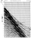
Allen, R., Fratta D., Introduction to applied geophysics, offer detailed lecture notes on the use of head waves in the seismic refraction method.
If the propagation velocity depends only on depth (stratified medium with horizontal interfaces or vertical velocity gradient), the geometry of the rays is determined by Snell's law :
the ray parameter p, inverse of the horizontal apparent velocity (also called horizontal slowness), is constant.
The incidence angle θ(z) of the ray relative to the vertical (which is the common normal to all interfaces or isovelocity curves) increases or decreases with increases or decreases in velocity.
The horizontal distance X(p) travelled along a ray and the traveltime T(p) are expressed as a function of the parameter p by summing over depth intervals corresponding to layer thicknesses
in a stratified medium.
It is also useful to express τ(p) = T(p)-pX(p), which represents the vertical traveltime in the medium at the apparent vertical velocities corresponding to the parameter p.
In a medium with a velocity gradient, the discrete summation is replaced by an integration over infinitesimal depth intervals dz.
If the velocity gradient a is a constant (V(z) = V0+az), the rays are circles centered at the depth z = -V0/a where V(z) = 0.
In this case, the wavefronts are also circles. They are the circles orthogonal to the family of ray circles, all centered on the Oz axis (for a source placed at the origin), at depths increasing with time.
In the limit of small incidence angles, T(X) can be approximated with an hyperbolic expression analogous to that in a medium of constant velocity.
The velocity of the equivalent medium is VRMS. This approximation is commonly used in the processing of seismic reflection data.
| Snell's law : p = sinθ/V = (1/Vax) = cte for a ray | ray parameter | horizontal distance X(p) between two points of a same ray of parameter p | traveltime T(p) between two points of a same ray of parameter p
vertical traveltime τ(p) at vertical apparent velocity |
stratified medium with plane horizontal interfaces (layers with thicknesses di and constant velocities Vi)
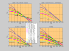 - -
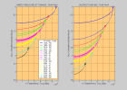
hodostratif.m - hodostrat.m | p = sinθi/Vi | X(p) = ∑ditanθi = p∑diVi/(1-p2Vi2)½ | T(p) = ∑di/cosθiVi = ∑di/(1-p2Vi2)½Vi
τ(p) = T(p)-pX(p) = ∑dicosθi/Vi = ∑di(1-p2Vi2)½/Vi |
| velocity gradient V(z)
for a positive gradient, the ray reaches a maximum depth Zmax(p) | p = sinθ(z)/V(z) = 1/V(Zmax) | X(p) = p∫dzV(z)/(1-p2V(z)2)½ | T(p) = ∫dz/(1-p2V(z)2)½V(z)
τ(p) = ∫dz(1-p2V(z)2)½/V(z) |
| case V(z) = V0+az
the rays are circles of radius R(p)=1/(ap) centered at z = -V0/a where V(z) = 0 | sinθ(z) = (V0/a+z)/R = pV(z) | X(p) = R[cosθ] = R[(1-p2V(z)2)½] | T(p) = ∫Rdθ/V(z(θ)) = (1/a)∫dθ/sinθ = (1/a)[Log(tan(θ/2))] = (1/a)[Log(pV(z)/(1+(1-p2V(z)2)½))] |
| case V(z) = V0+az
the wavefronts at times T = -(1/a)[Log(tan(θ0/2))] are the circles orthogonal to the rays the equation of the wavefronts is x2+(z-Zmax(T))2 = X(T)2 
hodovz.m | tan(θ0/2) = e-aT | X(T) = V0/atanθ0 = (V0/2a)(eaT-e-aT)
X(T) = (V0/a)sinh(aT) | Zmax(T) = (V0/a)(1/sinθ0-1) = (V0/2a)(eaT+e-aT-2)
Zmax(T) = (V0/a)(cosh(aT)-1) |
VRMS approximation for small incidence angles
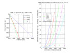
vrms.m | θ ≈ 0 p ≈ θi/Vi | X(p) ≈ p∑diVi | T(p) ≈ ∑di(1+p2Vi2/2)/Vi = ∑di/Vi+(p2/2)∑diVi = T(X=0)+X2/2∑diVi |
| T(X)2 ≈ T(0)2+X2/VRMS2
VRMS2 = (∑diVi)/(∑di/Vi) = (∫V(z)dz)/(∫dz/V(z)) VRMS(V0+az) = (a(V0z+az2/2)/Log(1+az/V0))½ | |||
V(z) generally increases with depth. The rays originating from a point source are curved toward the surface and reach it at increasing horizontal distances
for incidence angles θ0 decreasing from 90° (ray departing horizontally from the source) to 0° (ray departing vertically from the source).
The wavefront reaches the surface with an increasing apparent horizontal velocity.
If the velocity gradient has a large increase in a depth interval, the traveltime curve shows a triplication.
If the velocity gradient has a sign change in a depth interval, there is a shadow zone where no geometrical ray penetrates. In the corresponding X interval, no ray reaches the surface.
If the source is situated in a low velocity zone, the rays that bottom and top in the zone never leave it. The low velocity zone acts as a waveguide.
A plane wavefront incident on a depth interval where V(z) increases with depth is totally reflected
if the bottom point of the rays is in the interval.
Lutter W.J., R. D. Catchings and C. M. Jarchow, 1994,
An image of the Columbia Plateau from inversion of high-resolution seismic data show the effect of a stratification basalt (5 km/s) - sediment (4 km/s) - basement (5.5 km/s) on first arrivals.
Hornby B., 1993,
Tomographic reconstruction of near-borehole slowness using refracted borehole sonic arrivals is an example of the use of head and refracted waves in seismic logging.
Russel D., Refraction of sound in the atmosphere
Garcés, M.A., Hansen, R. A. & Lindquist, K.G., 1998,
Traveltimes for infrasonic waves propagating in a stratified atmosphere
| e = -cosθ1n+sinθ1m | er = cosθ1n+sinθ1m | er-e = 2cosθ1n = -2(e.n)n | er = e-2(e.n)n |
| e/V1 = -cosθ1/V1n+sinθ1/V1m | et/V2 = -cosθ2/V2n+sinθ2/V2m | et/V2-e/V1 = (cosθ1/V1-cosθ2/V2)n | et = V2/V1(e-(e.n+((V1/V2)2-(1-e.n2))½)n) |
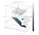
Here is an example for a medium including two dipping interfaces. The rays displayed are PP and PS reflections on the deepest interface. One can verify that the reflection points correspond to an extremum of the traveltimes.
 -
-
 -
-
refl3d.m
In the case of continuous variations of the propagation velocity with depth and lateral position, both the horizontal and vertical apparent velocities vary along a given ray.
The variation along a ray of the inverse of the apparent velocity in a given direction is equal to the component of the gradient of 1/V (called slowness) in this direction.
This relationship allows tracing rays by numerical integration with respect to the arclength along the ray and computing at each integration step the new propagation direction e.
In the case where V(x,z) varies linearly with x and z, the seismic rays are circles centered on the straigth line of equation V(x,z) = 0.
| position x(s) along the ray as a function of arclength s
e = dx/ds | differential equation of the rays
e.e = 1 , e.∂e/∂x = 0 , gradT.∂e/∂x = 0 ∂(dT/ds)/∂x = ∂(e.gradT)/∂x = e.grad∂T/∂x = d(∂T/∂x)/ds | curvature of rays de/ds = eN/R | torsion of rays
b = e∧eN deN/ds = -e/R-b/τ |
| gradT = e/V
T = ∫ds/V(x(s)) | d(e/V)/ds = d(gradT)/ds = grad(dT/ds) = grad(1/V) | 1/R = VeN.grad(1/V) | 1/τ = -Rb.d(Vgrad(1/V))/ds |
|
case V(x,z) = V0+axx+azz = V0+a(xsinα+zcosα)
by a rotation with angle α, one gets back to the case V(Z) = V0+aZ seismic rays are circles centered on the straigth line of equation V(x,z) = 0 |
d(sinθ/V)/ds = -ax/V2 = -asinα/V2
d(cosθ/V)/ds = -az/V2 = -acosα/V2 | 1/R = dθ/ds = -axcosθ/V+azsinθ/V = asin(θ-α)/V |
One can derive ray equations directly from the wave equation for a V(x) medium by looking for solutions expressed as quasi-plane harmonic waves with wavefront T(x) and amplitude A(x). One gets terms depending on successive powers of the angular frequency ω. The term in ω2, dominant at high frequency, gives the eikonal equation of traveltimes. It can be solved numerically in heterogeneous media by a finite difference method. The term in ω gives the transport equation that determines the variation of the amplitude A(x).
| wave equation | quasi-plane wave | term in ω2 → eikonal equation | term in ω → transport equation | ray tube with section dS(s) |
| Δφ+(ω/V(x))2φ = 0 | φ = A(x)eiω(T(x)-t) | gradT.gradT=1/V2 | 2gradA.gradT+AΔT = div(A2gradT) = 0 | ∫∫∫div(A2gradT)dυ = ∫∫(A2/V)e.dσ = 0
A2dS/V = cte |
Langan, R.T., I. Lerche, and R. T. Cutler , 1985, Tracing of rays through heterogeneous media: An accurate and efficient procedure
Bernasconi G. and G. Drufuca, 2001, 3-D traveltimes and amplitudes by gridded rays
give a simple method of 3D ray-tracing by a finite-difference method.
Sava P. and S. Fomel, M. 2001, 3-D traveltime computation using Huygens wavefront tracing
| ω and kx = ωp = ωsin(θ)/VP = ωsin(η)/VS of the incident wave are the same for all reflected and transmitted waves on a plane horizontal interface | ||
|
downgoing waves :
kzP = +ωcos(θ)/VP , kzS = +ωcos(η)/VS
upgoing waves : kzP = -ωcos(θ)/VP , kzS = -ωcos(η)/VS | SH waves | P-SV waves |
| free surface | σzyIncident SH+σzyReflected SH = 0 |
σzzIncident P or SV+σzzReflected P+σzzReflected SV = 0
σzxIncident P or SV+σzxReflected P+σzxReflected SV = 0 |
| solid - solid interface |
uy Incident SH+uy Reflected SH = uy Transmitted SH
σzyIncident SH+σzyReflected SH = σzyTransmitted SH |
uxIncident P or SV+uxReflected P+uxReflected SV =
uxTransmitted P+uxTransmitted SV
uzIncident P or SV+uzReflected P+uzReflected SV = uzTransmitted P+uzTransmitted SV σzzIncident P or SV+σzzReflected P+σzzReflected SV = σzzTransmitted P+σzzTransmitted SV σzxIncident P or SV+σzxReflected P+σzxReflected SV = σzxTransmitted P+σzxTransmitted SV |
| liquid - solid interface | . |
uzIncident P+uzReflected P =
uzTransmitted P+uzTransmitted SV
σzzIncident P+σzzReflected P = σzzTransmitted P+σzzTransmitted SV σzxTransmitted P+σzxTransmitted SV = 0 |
| Snell's law :
kx = ωp = ωsinη1/VS1 = ωsinη2/VS2 | incident downgoing SH wave | reflected upgoing SH wave | transmitted downgoing SH wave | |
|
particle motion SH wave
uy(x,z,t) = Uyeikzzei(kxx-ωt) |
UyI = 1 kzI = ωcosη1/VS1 |
UyR = R kzR = -ωcosη1/VS1 |
UyT = T kzT = ωcosη2/VS2 | |
|
stress on horizontal surface
σzy(x,z,t) = μ∂uy/∂z = ρVS2ikzuy = iωSzyeikzzei(kxx-ωt) | SzyI = ρ1VS1cosη1 | SzyR = -ρ1VS1cosη1R | SzyT = ρ2VS2cosη2T | |
| continuity on interface z =0
(uyI+uyR)(z=0) = uyT(z=0) (σzyI+σzyR)(z=0) = σzyT(z=0) |
1+R=T
(1-R)ρ1VS1cosη1 = Tρ2VS2cosη2 |
R = (ρ1VS1cosη1-ρ2VS2cosη2)/(ρ1VS1cosη1+ρ2VS2cosη2)
T = 2ρ1VS1cosη1/(ρ1VS1cosη1+ρ2VS2cosη2) | ||
|
weak contrast
ρ+δρ , V+δV δη = tanηδV/V (δp=0) | R ≈ -δ(ρVcosη)/2ρVcosη = -(1/2)(δρ/ρ+(1-tg2η)δV/V) | T ≈ 1 | ||
|
total reflection
sinηc=VS1/VS2 η1>ηc , pVS2>1 |
kzR = -kzI = -ω(1-p2VS12)½/VS1
R = (ρ1VS1(1-p2VS12)½-iρ2VS2(p2VS22-1)½)/(ρ1VS1(1-p2VS12)½+iρ2VS2(p2VS22-1)½) R = eiχ(p) , χ(p) = -2Arctan(ρ2VS2(p2VS22-1)½/ρ1VS1(1-p2VS12)½) (uyI+uyR)(x,z,t) = (eikzIz+ei(kzRz+χ(p)))ei(kxx-ωt) = 2cos(kzIz-χ(p)/2)ei(kxx-ωt+χ(p)/2) |
transmitted evanescent wave : kzT = iω(p2VS22-1)½/VS2
T = 2ρ1VS1(1-p2VS12)½/(ρ1VS1(1-p2VS12)½+iρ2VS2(p2VS22-1)½) T = ||T||eiχ(p)/2 uyT(x,z,t) = ||T||e-ωz(p2VS22-1)½/VS2ei(kxx-ωt+χ(p)/2) | ||
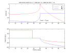
Here are the reflection and transmission coefficients and the particle motion computed as a function of incidence angle in the case of partial and total reflection :
 -
-
reflsh.m
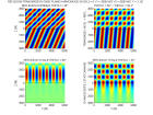
Here is an animation in the case of a reflection on a free surface (R=1) that produces standing waves along depth with nodes (zero) of stress for z = nπ/kz and antinodes (maxima) at z = (n+1/2)π/kz.
Ocean Acoustics Library : total reflection of a plane wave on a plane interface
| Snell's law : kx = ωp = ωsinθ1/VP1 = ωsinη1/VS1 = ωsinθ2/VP2 = ωsinη2/VS2 | ||||
| P incident downgoing ΦI = 1 kzI = ωcosθ1/VP1 | P reflected upgoing ΦR = Rφ kzP = -ωcosθ1/VP1 | SV reflected upgoing ΨR = Rψ kzS = -ωcosη1/VS1 | P transmitted downgoing ΦT = Tφ kzP = ωcosθ2/VP2 | SV transmitted downgoing ΨT = Tψ kzS = ωcosη2/VS2 |
| Ux = p | + pRφ | + (cosη1/VS1)Rψ | = pTφ | -(cosη2/VS2)Tψ |
| Uz = cosθ1/VP1 | -(cosθ1/VP1)Rφ | + pRψ | = (cosθ2/VP2)Tφ | + pTψ |
| Szz = ρ1(1-2p2VS12) | + ρ1(1-2p2VS12)Rφ | - (2ρ1VS12pcosη1/VS1)Rψ | = ρ2(1-2p2VS22)Tφ | + (2ρ2VS22pcosη2/VS2)Tψ |
| Szx = -2ρ1VS12pcosθ1/VP1 | + (2ρ1VS12pcosθ1/VP1)Rφ | + ρ1(1-2p2VS12)Rψ | = -(2ρ2VS22pcosθ2/VP2)Tφ | + ρ2(1-2p2VS22)Tψ |
| matrix notation case liquid-solid | AR = B ; R = [Rφ , Rψ , Tφ , Tψ]t ;
B = [-p , -cosθ1/VP1 , -ρ1(1-2p2VS12) , 2ρ1VS12pcosθ1/VP1]t
ALRL = BL ; RL = [Rφ , Tφ , Tψ]t ; BL = [-cosθ1/VP1 , -ρ1 , 0]t | |||
| A[4,4]
AL[3,3] | p | cosη1/VS1 | -p | cosη2/VS2 |
| -cosθ1/VP1 | p | -cosθ2/VP2 | -p | |
| ρ1(1-2p2VS12) (ρ1) | -2ρ1VS12pcosη1/VS1 | -ρ2(1-2p2VS22) | -2ρ2VS22pcosη2/VS2 | |
| 2ρ1VS12pcosθ1/VP1 (0) | ρ1(1-2p2VS12) | 2ρ2VS22pcosθ2/VP2 | -ρ2(1-2p2VS22) | |
P incident downgoing or upgoing

reflpsv.m |
Rφ = det([B,A[:,2:4]])/det(A)
tφ = det([b,A[:,2:4]])/det(A) |
Rψ = det([A[:,1],B,A[:,3:4]])/det(A)
tψ = det([A[:,1],b,A[:,3:4]])/det(A) |
Tφ = det([A[:,1:2],B,A[:,4]])/det(A)
rφ = det([A[:,1:2],b,A[:,4]])/det(A) |
Tψ = det([A[:,1:3],B])/det(A)
rψ = det([A[:,1:3],b])/det(A) |
|
P incident downgoing
D = det(A) = P-Q Rφ = (-P-Q)/D Rψ =2S/D |
AR = B ; R = [Rφ , Rψ , Tφ , Tψ]t ;
B = [-p , -cosθ1/VP1 , -ρ1(1-2p2VS12) , 2ρ1VS12pcosθ1/VP1]t = [-a11 , a21 , -a31 , a41]t ; D = (a11A11+a31A31)-(a21A21+a41A41) ; DRφ = -(a11A11+a31A31)-(a21A21+a41A41) DRψ/2 = a11a21(a33a44-a43a34) +a11a41(a23a34-a33a24) +a31a41(a13a24-a23a14) DTφ/2 = -(a11a21(a32a44-a42a34) +a11a41(a22a34-a32a24) +a31a41(a12a24-a22a14)) DTψ/2 = (a11a21(a32a43-a42a33) +a11a41(a22a33-a32a23) +a31a41(a12a23-a22a13) | |||
| P incident upgoing
kzI = -ωcosθ2/VP2 |
Ar = b ; r = [tφ,tψ,rφ,rψ]t
b = [p , -cosθ2/VP2 , ρ2(1-2p2VS22) , 2ρ2VS22pcosθ2/VP2]t = [-a13 , a23 , -a33 , a43]t D = (a13A13+a33A33)-(a23A23+a43A43) ; Drφ = -(a13A13+a33A33)-(a23A23+a43A43) Drψ/2 = a13a23(a31a42-a41a32) +a13a43(a21a32-a31a22) +a33a43(a11a22-a21a12) Dtφ/2 = -(a13a23(a34a42-a44a32) +a13a43(a24a32-a34a22) +a33a43(a14a22-a24a12)) Dtψ/2 = a13a23(a34a41-a44a31) +a13a43(a24a31-a34a21) +a33a43(a14a21-a24a11) | |||
case liquid-solid

reflpsl.m |
ALRL = BL ; RL = [RφL , TφL , TψL]t ;
BL = [-cosθ1/VP1 , -ρ1 , 0]t
ALrL = bL ; rL = [tφL , rφL , rψL]t ; bL = [-cosθ2/VP2 , ρ2(1-2p2VS22) , 2ρ2VS22pcosθ2/VP2]t DL = -ρ22cosθ1/VP1((1-2p2VS22)2+4VS24p2cosθ2/VP2cosη2/VS2) -ρ1ρ2cosθ2/VP2 DLRφL = -ρ22cosθ1/VP1((1-2p2VS22)2+4VS24p2cosθ2/VP2cosη2/VS2) +ρ1ρ2cosθ2/VP2 DLTφL = -2ρ1ρ2cosθ1/VP1(1-2p2VS22) ; DLtφL = -2ρ22cosθ2/VP2(1-2p2VS22) DLTψL = -4ρ1ρ2cosθ1/VP1VS22pcosθ2/VP2 | |||
SV incident downgoing or upgoing

reflpsv.m |
R'φ = det([B',A[:,2:4]])/D
t'φ = det([b',A[:,2:4]])/D |
R'ψ = det([A[:,1],B',A[:,3:4]])/D
t'ψ = det([A[:,1],b',A[:,3:4]])/D |
T'φ = det([A[:,1:2],B',A[:,4]])/D
r'φ = det([A[:,1:2],b',A[:,4]])/D |
T'ψ = det([A[:,1:3],B'])/D
r'ψ = det([A[:,1:3],b'])/D |
| SV incident downgoing
ΨI = 1 ; kzI = ωcosη1/VS1 D = det(A) = -P'+Q' R'ψ = (-P'-Q')/D |
AR'=B' ; R' = [R'φ , R'ψ , T'φ , T'ψ]t ;
B' = [cosη1/VS1 , -p , -2ρ1VS12pcosη1/VS1 , -ρ1(1-2p2VS12)]t = [a12 , -a22 , a32 , -a42]t ; D = -(a12A12+a32A32)+(a22A22+a42A42) ; DR'ψ = -(a12A12+a32A32)-(a22A22+a42A42) | |||
| SV incident upgoing
kzI = -ωcosη2/VS2 |
Ar'=b' ; r' = [t'φ , t'ψ , r'φ , r'ψ]t
b' = [cosη2/VS2 , p , -2ρ2VS22pcosη2/VS2 , ρ2(1-2p2VS22)]t = [a14 , -a24 , a34 , -a44]t ; D = -(a14A14+a34A34)+(a24A24+a44A44) Dr'ψ = -(a14A14+a34A34)-(a24A24+a44A44) | |||
| total reflection of downgoing SV wave
p = sinη1/VS1 1/VS1 > p > 1/VP1 p > 1/VS2 > 1/VP2 R'ψ = eiχ'(p) |
imaginary terms of A :
a14 = i(p2VS22-1)½/VS2 ;
a21 = -i(p2VP12-1)½/VP1 ;
a23 = -i(p2VP22-1)½/VP2 ;
a34 = -2iρ2VS22p(p2VS22-1)½/VS2 ; a41 = 2iρ1VS12p(p2VP12-1)½/VP1 ; a43 = 2iρ2VS22p(p2VP22-1)½/VP2 ; ⇒ A12, A32 and P' are imaginary, A12, A32 and Q' are real R'ψ = (-P'-Q')/(-P'+Q') = eiχ'(p) χ'(p) = 2Arctan(P'/iQ') = 2Arctan((1/i)(a12A12+a32A32)/(a22A22+a42A42)) | |||
Here are the moduli of the reflection-transmission coefficients P-SV and SV-P computed for incidence angles of 0°, 15° and 30° in water for a sedimentary stratified medium :
 -
-

| weak contrasts |
ρ2 = ρ+δρ ;
VP2 = VP+δVP ;
θ2 = θ+δθ ; δθ = tanθδVP/VP ;
VS2 = VS+δVS ;
η2 = η + δη ; δη = tanηδVS/VS
a11 = -a13 = a22 = -a24 = p ; a12 = cosη/VS ; a21 = -cosθ/VP ; a31 = a42 = ρ(1-2p2VS2) ; a32 = -2ρVS2pcosη/VS ; a41 = 2ρVS2pcosθ/VP a14 = (a12+δa12) ; a23 = (a21+δa21) ; a33 = a44 = -(a31+δa31) ; a34 = (a32+δa32) ; a43 = (a41+δa41) |
| D = det(A) |
D =
(p2-a21a12)(a312-a41a32)
- (2pa21)(-2a31a32)
+ (-p2-a21a12)(a32a41+a312)
+ (a12a21+p2)(-a312-a41a32)
- (-2pa12)(2a31a41)
+ (p2-a21a12)(a312-a41a32)
D = 2(p2-a21a12)(a312-a41a32) -2(p2+a21a12)(a32a41+a312) +4pa31(a21a32+a12a41) = -4p2a41a32 -4a21a12a312 +4pa31(a21a32+a12a41) D = 4cosθ/VPcosη/VS [p2(2ρVS2p)2 +(ρ(1-2p2VS2))2 +4ρ2p2VS2(1-2p2VS2)] = 4ρ2cosθ/VPcosη/VS |
| Rφ |
DRφ =
(-p2-a21a12)((a31+δa31)2-(a41+δa41)(a32+δa32))
- (-p(a21+δa21)+pa21)(-a32(a31+δa31)-a31(a32+δa32))
+ (p2-a21(a12+δa12))(a32(a41+δa41)+a31(a31+δa31)) +
(a12(a21+δa21)+p2)(a31(a31+δa31)-a41(a32+δa32))
- (-pa12-p(a12+δa12))(-a31(a41+δa41)+a41(a31+δa31))
+ (p2-(a21+δa21)(a12+δa12))(-a312-a41a32))
DRφ = (-p2-a21a12)(2a31δa31-a41δa32-a32δa41) - 2pa32a31δa21 + (p2-a21a12)(a32δa41+a31δa31)-a21δa12(a32a41+a312) + (p2+a12a21)(a31δa31-a41δa32)+a12δa21(a312-a41a32) + 2pa12(-a31δa41+a41δa31) + (a21δa12+a12δa21)(a312+a41a32) DRφ = 2(p(pa32-a12a31)δa41 + a12(pa41-a21a31)δa31 + a31(a31a12-pa32)δa21)
DRφ =
2ρ(-2p2cosη/VSδ(ρVS2cosθ/VP)
+cosη/VScosθ/VPδ(ρ(1-2p2VS2)
+ ρ(1-2p2VS2)cosη/VSδ(-cosθ/VP))
Rφ =
(1/2)((1-4p2VS2)δρ/ρ
- 8p2VS2δVS/VS
- δ(cosθ/VP)/(cosθ/VP))
|
| Rψ |
DRψ =
(2pa21)((a31+δa31)2-(a41+δa41)(a32+δa32))
- p((a21+δa21)+a21)(a31(a31+δa31)-a41(a32+δa32))
+ (-p2-a21(a12+δa12))(-a31(a41+δa41)+a41(a31+δa31)) +
p(-(a21+δa21)+a21)(-a31(a31+δa31)-a41(a32+δa32))
- (p2-a21(a12+δa12))(a31(a41+δa41)+a41(a31+δa31))
+ (p2-(a21+δa21)(a12+δa12))(2a31a41)
DRψ = 2pa21(2a31δa31-a41δa32-a32δa41) - 2pa21(a31δa31-a41δa32)-pδa21(a312-a41a32) + (-p2-a21a12)(-a31δa41)+a41δa31)) + (-pδa21)(-a312-a41a32) - (p2-a21a12)(a31δa41+a41δa31) +a21δa122a31a41 + (-2a31a41(a21δa12+a12δa21)) DRψ = 2(p(a21a31-pa41)δa31 + a21(-pa32+a12a31)δa41 + a41(pa32-a31a12)δa21)
DRψ =
-2ρpcosθ/VP(δ(ρ(1-2p2VS2))
+ cosη/VSδ(2ρVS2cosθ/VP)
+ 2ρVS2cosη/VSδ(-cosθ/VP))
Rψ =
-(1/2)pVS/cosη
((1-2p2VS2+2VS2cosθ/VPcosη/VS)δρ/ρ
+ 4VS2(-p2+cosη/VScosθ/VP)δVS/VS)
|
In a similar way, an interface (z = 0) between two elastic half-spaces can guide a Stoneley wave (only for some values of velocities and densities). It is made of two coupled Rayleigh waves (two P1, SV1 evanescent waves for z ≤ 0 coupled to two P2 , SV2 evanescent waves for z ≥ 0) propagating at the same horizontal velocity. VST is determined by looking for roots of the determinant of the matrix A obtained in the computation of the reflection-transmission coefficients for P-SV waves. There is not always a solution , except in the liquid-solid case.
| Stoneley equation liquid-solid interf. | DL = -ρ22cosθ1/VP1((1-2p2VS22)2+4VS24p2cosθ2/VP2cosη2/VS2)
-ρ1ρ2cosθ2/VP2 = 0
(1-2p2VS22)2-4VS24p2(p2VP22-1)½/VP2(p2VS22-1)½/VS2 + (ρ1/ρ2)((p2VP22-1)½/VP2)/((p2VP12-1)½/VP1) = 0 |
Stephen, R.A., F. Cardo-Casas, and C. H. Cheng , 1985, Finite-difference synthetic acoustic logs show the propagation of a Stoneley wave in a well for sonic logging.

|
standing wave in z
kz for normal modes |
travelling wave in x , kx = (ω2/VS2-kz2)½
phase velocity V(ω) = Vax = ω/kx |
ω ≥ high-frequency cut-off ωc
kx real for travelling wave in x |
|
normal modes 1D
C, C, G, C, E, G... |
eikz+e-ikz = 2cos(kz)
Hkn = nπ , nλn/2 = H , n = 1,2,3... | ||
|
slab with free surfaces
Rsup = Rinf = 1 |
eikzz+e-ikzz = 2cos(kzz)
Hkz n = nπ , nλz n/2 = H , n = 1,2,3... |
kx n = (ω2/VS2-(nπ/H)2)½
Vn(ω) = ω/kx n | ωc n = nπVS/H |
|
layer (-H ≤ z ≤ 0)
over half-space (z≥ 0) Rsurf = 1 ; Rinterf = eiχ(p) |
eik1zz+eiχ(p)e-ik1zz = 2eiχ(p)/2cos(k1zz-χ(p)/2)
Hk1z n+χ(p)/2 = nπ , n = 0,1,2,3... |
kx n = (ω2/VS12-(nπ-χ(p)/2)2/H2)½
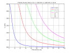
VL n(ω) = ω/kx n = 1/pn |
kx nc = ωc n/VS2 ; χ(1/VS2) = 0
ωc n = nπ/(H(1/VS12-1/VS22)½) |
displov.m |
k1z = (ω/VS1)(1-p2VS12)½
χ(p) = -2Arctan(ρ2VS2(p2VS22-1)½/ρ1VS1(1-p2VS12)½) = -2Arctan(I2/I1)
dispersion relation of Love wave :
| ||
An SV wave totally reflected in a layer such that VS1<VS2<VP1<VP2 produces a guided Rayleigh wave. It propagates at the velocity VR that is the apparent horizontal velocity of the SV waves in the layer, such that VS1≤VR≤VS2. The total reflection on the free surface produces a phase-shift χ'1(p) computed for P-SV reflection coefficients on a free surface. The total reflection on the interface with the Half-space produces a phase-shift χ'2(p) computed for P-SV reflection coefficients at the interface. The dispersion relation is written by taking into account the sum χ'12(p) of these two phase-shifts for the standing wave condition in the layer. One obtains in this way the dispersion relation for the harmonics (n≥1 , VS1≤VRn≤VS2, VRn=VS2 at the cut-off frequency fcn) of the Rayleigh wave guided in the layer.
| boundary conditions | normal modes in z | travelling wave in x | cut-off frequency |
| Rsurf = eiχ'1(p)
Rinterf = eiχ'2(p) χ'12(p) = χ'1(p)+χ'2(p) | (n-χ'12(p)/2π)λ1z n/2 = H
Hk1z n+χ'12(p)/2 = nπ | kx n = (ω2/VS12-(nπ-χ'12(p)/2)2/H2)½
VR n(ω) = ω/kx n = 1/pn | ωc n = (nπ-χ'12(1/VS2))/2)/(H(1/VS12-1/VS22)½) |
| dispersion rel. of Rayleigh wave overtones n≥1 VS1≤VR n≤VS2 |
χ'1(p) = -2Arctan((4VS14p2(p2VP12-1)½/VP1(1-p2VS12)½/VS1)/(1-2p2VS12)2) =
-2Arctan(S)
χ'2(p) = -2Arctan(Im(D)/Re(D)) = -2Arctan(I) tan(Hω(1-p2VS12)½/VS1) = -tan((χ'1(p)+χ'2(p))/2) = (I+S)/(1-IS) ω(pn) = (-(χ'1(pn)+χ'2(pn))/2+nπ)VS1/(H(1-pn2VS12)½) = (Arctan((I+S)/(1-IS))+nπ)VS1/(H(1-pn2VS12)½) | ||
The dispersion relation of the fundamental mode of the Rayleigh wave is obtained by considering four upgoings and downgoings P and SV waves in the layer and two evanescent P and SV waves in the half-space. The propagation velocity VR0 correspond to the root of the determinant of the matrix expressing the boundary conditions on the free surface in z = -H and on the interface on z = 0. It is such that VRS1≤VR0≤VRS2 where VRS1is the Rayleigh wave velocity guided at the free surface of a half-space of velocity VS1 and VRS2 that for a half-space of velocity VS2. At low frequency, VR0 = VRS2 (the wave with wavelength >> H does not see the layer).
| boundary cond. | downgoing P1 , kzP1 = ω(1-p2VP12)½/VP1
ZP1 = e-ikzP1H | downgoing S1 , kzS1 = ω(1-p2VS12)½/VS1
ZS1 = e-ikzS1H | upgoing P1 , -kzP1 | upgoing S1 , -kzS1 | evanescent P2 , kzP2 = iω(p2VP22-1)½/VP2 | evanescent S2 , kzS2 = iω(p2VS22-1)½/VS2 |
| z = -H | σzz(kzP12)ZP1 | -2μ1kxkzS1ZS1 | σzz(kzP12)/ZP1 | 2μ1kxkzS1/ZS1 | 0 | 0 |
| -2μ1kxkzP1ZP1 | σzx(kzS12)ZS1 | 2μ1kxkzP1/ZP1 | σzx(kzS12)/ZS1 | 0 | 0 | |
| z = 0 | kx | -kzS1 | kx | kzS1 | -kx | kzS2 |
| kzP1 | kx | -kzP1 | kx | -kzP2 | -kx | |
| σzz(kzP12) | -2μ1kxkzS1 | σzz(kzP12) | 2μ1kxkzS1 | -σzz(kzP22) | 2μ2kxkzS2 | |
| -2μ1kxkzP1 | σzx(kzS12) | 2μ1kxkzP1 | σzx(kzS12) | 2μ2kxkzP2 | -σzx(kzS22) |
The high-frequency part of the dispersion relation of the fundamental mode (VRS1≤VR0≤VS1) corresponds to the Rayleigh wave guided by the free surface of the layer coupled to a Stoneley wave guided by the interface (or two P and SV evanescent waves in the layer from the surface coupled to four evanescent waves from the interface). At high-frequency, VR0 = VRS1 (the wave with wavelength << H sees only the layer).
| boundary cond. | waves guided by free surface in z = -H and prolongated in z = 0 by
ZP1 = e-ω(p2VP12-1)½/VP1H (0) ; ZS1 = e-ω(p2VS12-1)½/VS1H (0) | waves guided by interf. in z = 0 and prolongated in z = -H by ZP1 , ZS1 | ||||
| z = -H | Rayleigh free surf. | (1-2p2VS12)ZP1 (0) | -i2pVS1(p2VS12-1)½ZS1 (0) | 0 | 0 | |
| +i2VS12p(p2VP12-1)½/VP1ZP1 (0) | +(1-2p2VS12)ZS1 (0) | 0 | 0 | |||
| z = 0 | pZP1 (0) | -i(p2VS12-1)½/VS1ZS1 (0) | Stoneley at interface | |||
| i(p2VP12-1)½/VP1ZP1 (0) | pZS1 (0) | |||||
| ρ1(1-2p2VS12)ZP1 (0) | i2ρ1VS12p(p2VS12-1)½/VS1ZS1 (0) | |||||
| -i2ρ1VS12p(p2VP12-1)½/VP1ZP1 (0) | ρ1(1-2p2VS12)ZS1 (0) | |||||
Russel D., Waveguide
| superposition of harmonic waves of phase velocities V(ω)=ω/k | constructive interference in (x,t) ⇔ stationnary phase for harmonic waves (the U variation is negligible) ⇒ group velocity Vg |
| u(x,t) = ∫U(ω)eiω(x/V(ω)-t)dω = ∫U(ω)ei(k(ω)x-ωt)dω = ∫U(k)ei(kx-ω(k)t)dk | d(k(ω)x-ωt)/dω = (dk/dω)x-t = 0 ⇒ Vg = dω/dk = V+kdV/dk = 1/(dk/dω) = 1/(p+ωdp/dω) |
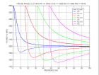 - -
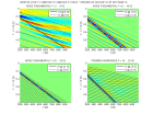
displov.m |
dispersion relation of Love wave : tan(Hω(pn)(1-pn2VS12)½/VS1) = (ρ2VS2(p2VS22-1)½)/(ρ1VS1(1-p2VS12)½)
differentiation of dispersion relation :
dpn/dω = (H/VS1)(1-pn2VS12)/
|
Kelly K.R. , 1983, Numerical study of Love wave propagation
Roth M. and K. Holliger, 1999, Inversion of source-generated noise in high-resolution seismic data
|
z
Ii = ρiVSi2kiz |
downgoing wave ekizz
kiz = ω(1/VSi2-p2)½ | upgoing wave e-ikizz |
continuity of uy and σyz at interface
total reflection if free surface (upgoing = downgoing) : dispersion relation |
|
-(h3+h2+h1)
layer 3 | D3e-ik3zh3 = D3(a3-ib3) | M3eik3zh3 = M3(a3+ib3) |
A3b3+a3B3 = 0
tan(k3zh3)+(I2/I3)tan(k2zh2)+((I1/I3)-(I1/I2)tan(k3zh3)tan(k2zh2))tan(k1zh1+χ/2) = 0 |
|
-(h2+h1)
layer 3 | D3 = A3-iB3 | M3 = A3+iB3 |
A3 = A2a2-B2b2 = a1a2-(I1/I2)b1b2
B3 = (I2/I3)(A2b2+B2a2) = (I2/I3)a1b2+(I1/I3)b1a2 |
|
-(h2+h1)
layer 2 | D2e-ik2zh2 = D2(a2-ib2) | M2eik2zh2 = M2(a2+ib2) |
A2b2+a2B2 = 0
tan(k2zh2)+(I1/I2)tan(k1zh1+χ/2) = 0 |
|
-h1
layer 2 | D2 = A2-iB2 | M2 = A2+iB2 |
A2 = a1
B2 = (I1/I2)b1 |
|
-h1
layer 1 | D1e-ik1zh1 = a1-ib1 | M1eik1zh1 = a1+ib1 |
b1 = 0
sin(k1zh1+χ/2) = 0 |
|
0
layer 1 | D1 = e-iχ/2 | M1 = eiχ/2 | χ(p) = -2Arctan(ρVS(p2VS2-1)½/ρ1VS1(1-p2VS12)½) = -2Arctan(I/I1) |
|
> 0
1/2 space |
evanescent wave e-kzz
kz = |ω|(p2-1/V2)½ | ||
| Bessel equation | solution | derivative |
| r2d2f/dr2+rdf/dr+ (kr2r2-n2)f(r) = 0 |
f(r) = Hn(krr) = Jn(krr)+iYn(krr)
≈ (2/πkrr)½ei(krr-π/4-nπ/2)
Hn(ikrr) ≈ i-(n+1)(2/πkrr)½e-krr | dHn(krr)/dr = krHn-1(krr)-(n/r)Hn(krr) = (n/r)Hn(krr)-krHn+1(krr) |
In the absence of azimutal variation, the displacement potentials for P et S waves are :
| Δφ(r,z) = ∂2φ/∂r2+(1/r)∂φ/∂r+∂2φ/∂z2 = (1/VP2)∂2φ/∂t2 | φ(r,z) = f(r)ei(kzz-ωt) | kp2 = ω2/VP2-kz2 | f(r) = AH0(kpr) |
| Δψθ(r,z) = (1/VS2)∂2ψθ/∂t2 | ψθ(r,z) = g(r)ei(kzz-ωt) | ks2 = ω2/VS2-kz2 | g(r) = BH1(ksr) |
If there is an angular variation with θ, one has :
| Δφ(r,θ,z) = Δφ(r,z) + (1/r)2∂2φ/∂θ2 = (1/VP2)∂2φ/∂t2 | φ(r,θ,z) =f(r)cos(nθ)ei(kzz-ωt) | kp2 = ω2/VP2-kz2 | f(r) = AHn(kpr) |
| Δψr(r,θ,z) = (1/VS2)∂2ψr/∂t2 | ψr(r,z) = g(r)sin(nθ)ei(kzz-ωt) | ks2 = ω2/VS2-kz2 | g(r) = BHn+1(ksr) |
| Δψθ(r,θ,z) = (1/VS2)∂2ψθ/∂t2 | ψθ(r,z) = -g(r)cos(nθ)ei(kzz-ωt) | ||
| Δψz(r,θ,z) = (1/VS2)∂2ψz/∂t2 | ψz(r,z) = h(r)sin(nθ)ei(kzz-ωt) | h(r) = CHn(ksr) |
Displacements and strains on the wall of a cylindrical borehole
| ur = cos(nθ) | uθ = sin(nθ) | uz = cos(nθ) | εrr = cos(nθ) | εrθ = sin(nθ) | εrz = cos(nθ) | |
| Aei(kzz-ωt) | n/rHn(kpr)-kpHn+1(kpr) | -n/rHn(kpr) | ikzHn(kpr) | (n(n-1)/r2-kp2)Hn(kpr)+kp/rHn+1(kpr) | -n(n-0.5)/r2Hn(kpr)+nkp/rHn+1(kpr) | ikz(n/rHn(kpr)-kpHn+1(kpr)) |
| Bei(kzz-ωt) | ikzHn+1(ksr) | ikzHn+1(ksr) | -ksHn(ksr) | ikz(ksHn(ksr)-(n+1)/rHn+1(ksr)) | ikz(ks/2Hn(ksr)-(n+1)/rHn+1(ksr)) | (-nks/rHn(ksr)+(ks2-kz2)Hn+1(ksr))/2 |
| Cei(kzz-ωt) | n/rHn(ksr) | -n/rHn(ksr)+ksHn+1(ksr) | 0 | n(n-1)/r2Hn(ksr)-nks/rHn+1(ksr) | (-n(n-1)/r2+ks2/2)Hn(ksr)-ks/rHn+1(ksr) | (ikzn/2r)Hn(ksr) |
The P and S solutions in cylindrical coordinates are developped in : Sinha, B.K., E. Simsek, and S. Asvadurov, 2009 Influence of a pipe tool on borehole modes
Without body forces, the 3 equilibrium equations expressed in terms of the components of the particle displacement are :
ρ∂2u/∂t2 = (λ+μ)graddivu+μΔu where
Δu = (Δux, Δuy, Δuz) = grad(divu)-curl(curl(u))
The P wave equation, ∂2φ/∂t2 = VP2Δφ,
is obtained from these 3 equations by writing u = gradφ.
Indeed, Δgradφ = gradΔφ as curl(gradφ) = 0.
Therefore, ρgrad∂2φ/∂t2 = (λ+2μ)grad(Δφ).
The S wave equation, ∂2ψ/∂t2 = VS2Δψ,
is obtained from these 3 equations by writing u = curlψ with divψ = 0.
Indeed, Δcurlψ = -curlcurlcurlψ = curlΔψ as divcurlψ = 0 and divψ = 0.
Therefore, ρcurl∂2ψ/∂t2 = μcurlΔψ.
For a source due to a point force with a module F(t) (N) and a direction e, the force per unit volume (N/m3) is :
f = F(t)eδ(x) = -F(t)/(4π)eΔ(1/r) = -F(t)/(4π)Δ(e/r) =
-(F(t)/(4π))(graddiv(e/r)-curlcurl(e/r)).
Indeed, ∫δ(x)dx = 1 and
∫Δ(1/r)dx = ∫grad(1/r).dS =
(-1/r2)er.4πr2er = -4π
imply δ(x) = -1/(4π)Δ(1/r).
As e is constant, eΔ(1/r) = Δ(e/r).
In the harmonic case where the module of the force varies as a sinusoid of pulsation ω : F(t) = Fe-iωt.
θ being the angle between the direction e of the force and the radial direction er of propagation of the wave
from the point where the force applies, e = cosθer-sinθeθ.
One needs the expression of the differential operators
in spherical coordinates (r,&theta,ξ) :
gradφ(r,θ) = &partφ/∂rer+1/r&partφ/∂θeθ and
curl(ψ(r,θ)eξ) =
(1/r)(1/sinθ∂(sinθψ)/∂θer-∂(rψ)/∂reθ).
The equilibrium equations with the part of the source term producing P waves are :
ρgrad∂2φ/∂t2 = (λ+2μ)grad(Δφ)-(F(t)/(4π)(graddiv(e/r)
The P wave equation becomes :
∂2φ/∂t2 = VP2Δφ-(F(t)/4πρ)div(e/r).
It includes a source term proportional to
(dive/r) = grad(1/r).e = -1/r2er.e = -cosθ/r2
The amplitude of the displacement potential and of the displacement in the far field is thus proprtional to cosθ.
By writing the particle displacement potential as the divergence of a vector Φ(r)e, one separates the dependency in r et θ.
| u = gradφ(r,θ) | ∂2φ/∂t2 = VP2Δφ-(F(t)/4πρ)div(e/r) | φ(r,θ) = div(Φ(r)e) | ∂2Φ/∂t2 = VP2ΔΦ-F(t)/(4πρr) | ∂2(rΦ)/∂t2 = VP2∂2(rΦ)/∂r2-F(t)/(4πρ) |
| F(t) = Fe-iωt, k = ω/VP | ∂2(rΦ)/∂r2+k2(rΦ) = F/(4πρVP2) | Φ = F/(4πρVP2k2)(1-eikr)/r | φ = gradΦ(r).e = cosθ∂Φ/∂r = -Fcosθ/(4πρVP2k2)((ik-1/r)eikr/r+1/r2) | |
|
u =
cosθ∂2Φ/∂r2er-1/r∂Φ/∂rsinθeθ =
cosθ∂2Φ/∂r2er+1/r∂Φ/∂r(e-cosθer)
u = ( -F/(4πρVP2k2)) ((cosθ(2/r2-2ik/r-k2)er+1/r(ik-1/r)(e-cosθer))eikr/r) -(1/r3)(3cosθer-e)) | ucl = Fcosθer/(4πρVP2)eikr/r | ucp = -F/(4πρVP2)(e-3cosθer)((i/kr-1/(kr)2)eikr/r+1/r3) | ||
The equilibrium equations with the part of the source term producing S waves are :
ρcurl∂2ψ/∂t2 = μcurlΔψ+(F(t)/(4π))curlcurl(e/r).
The S wave equation becomes :
∂2ψ/∂t2 =VS2Δψ+(F(t)/(4πρ))curl(e/r).
It includes a source term proportional to
curl(e/r) = grad(1/r)∧e = -(1/r2)er∧e =
sinθeξ/r2
The amplitude of the displacement potential and of the displacement in the far field is thus proportional to sinθ.
By writing the particle displacement potential as the curl of a vector Ψ(r)e, one separates the dependency in r et θ.
| u = curlψ(r,θ) | ∂2ψ/∂t2 = VS2Δψ+(F(t)/4πρ)curl(e/r) | ψ(r,θ) = -curl(Ψ(r)e) | ∂2Ψ/∂t2 = VS2ΔΨ-F(t)/(4πρr) | ∂2(rΨ)/∂t2 = VS2∂2(rΨ)/∂r2-F(t)/(4πρ) |
| F(t) = Fe-iωt, k = ω/VS | ∂2(rΨ)/∂r2+k2(rΨ) = F/(4πρVS2) | Ψ = F/(4πρVS2k2)(1-eikr)/r | ψ(r,θ) = -gradΨ(r)∧e = sinθ∂Ψ/∂reξ = -Fsinθeξ/(4πρVS2k2)((ik-1/r)eikr/r+1/r2) | |
|
u = (1/r)(2cosθer∂Ψ/∂r-sinθeθ∂(r∂Ψ/∂r)/∂r) =
(1/r)(2(e+sinθeθ)∂Ψ/∂r-sinθeθ(∂Ψ/∂r+r∂2Ψ/∂r2))
u = -F/(4πρVS2k2) (1/r)((2(e+sinθeθ)(ik-1/r)-sinθeθ(-rk2-ik+1/r))eikr/r +(1/r2)(2e+3sinθeθ)) | ucl = -Fsinθeθ/(4πρVS2)eikr/r | ucp = F/(4πρVS2)(e-3cosθer) ((i/kr-1/(kr)2)eikr/r+1/r3) | ||
The contribution of the terms of displacement in the near and far field to the displacement and polarization of P and S waves at distances of the source of the order
of the wavelength are illustrated in these figures :
 -
-
 -
-
 -
-
force.m
| isotropic case : 2 elastic coef. λ and μ | transverse isotropy (symmetry axis Oz) : 5 elastic coef. | example for clays (x109Pa) |
|
σxx = c11εxx+c12εyy+c12εzz
σxy = (c11-c12)εxy c11 = λ+2μ , c12 = λ |
σxx = c11εxx+c12εyy+c13εzz ,
σyy = c12εxx+c11εyy+c13εzz
σzz = c13εxx+c13εyy+c33εzz σyz = 2c44εyz , σzx = 2c44εzx σxy = 2c66εxy , c66 = (c11-c12)/2 |
c11 = 45 , c12 = 10 , c13 = 8
c33 = 28 c44 = 11 c66 = (c11-c12)/2 = 17.5 |
| σ , ε applied on thinly stratified medium of thickness H | horizontal layers of thicknesses hi, pi = hi/H | anisotropic equivalent moduli |
|
layers compressed in series vertically : σzz ≠ 0
without lateral strain : εxx = εyy = 0 |
σzzi = σzz , εzzi = σzz/(λi+2μi)
εzz = ∑piεzzi = σzz∑pi/(λi+2μi) σxxi = σyyi = λiεzzi |
σzz = c33εzz
c33 = 1/∑pi/(λi+2μi) |
|
layers compressed in parallel horizontaly along x : σxx ≠ 0
without strain along y : εyy = 0 without average vertical strain : εzz = ∑piεzzi = 0 uniform strain along x : εxxi = εxx |
σxxi = (λi+2μi)εxx+λiεzzi
σxx = ∑piσxxi = εxx∑pi(λi+2μi)+∑piλiεzzi [1] σzzi = σzz , σzz = λiεxx+(λi+2μi)εzzi [2] [2] ⇒ σzz∑pi/(λi+2μi) = εxx∑piλi/(λi+2μi) + ∑piεzzi = εxx∑piλi/(λi+2μi) [3] [2,3] ⇒ ∑piλiεzzi = εxx((∑piλi/(λi+2μi))2/∑pi/(λi+2μi)-∑piλi2/(λi+2μi)) [4] |
σxx = c11εxx
[1,4] ⇒ c11 = c33(∑piλi/(λi+2μi))2+4∑piμi(λi+μi)/(λi+2μi) |
| layers sheared in series horizontally : σyz ≠ 0 |
σyz = 2μiεyzi
εyz = ∑piεyzi = (σyz/2)∑pi/μi |
σyz = 2c44εyz
c44 = 1/∑pi/μi |
|
layers sheared in parallel horizontally : σxy ≠ 0
uniform strain : εxyi = εxy |
σxyi = 2μiεxy
σxy = ∑piσxyi = 2∑piμiεxy |
σxy = 2c66εxy
c66 = ∑piμi , c12 = c11-2c66 |
|
layers compressed in parallel horizontally along x : σxx ≠ 0
without vertical stress : σzz = 0 without strain along y : εyy = 0 uniform strain along x : εxxi = εxx |
σxxi = (λi+2μi)εxx+λiεzzi
σzzi = σzz = 0 , λiεxx+(λi+2μi)εzzi = 0 εzz = ∑piεzzi = -εxx∑piλi/(λi+2μi) |
σzz = c13εxx+c33εzz = 0
c13 = c33(∑piλi/(λi+2μi)) |
Here is a plot of these different strain-stress states and the equivalent elastic moduli obtained for a stratification with an equal proportion of slow and fast layers :
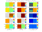
anisomod.m
| plane SH waves (horizontal polarization) | plane quasi-P waves (quasi-longitudinal polarization α : α ≈ θ)
plane quasi-SV waves (quasi-transverse polarization β : β ≈ η-π/2) |
| uy(x,z,t) = Uyei(kxx+kzz-ωt)
ρω2 = (c66kx2+c44kz2) the dispersion is an ellipse with semi-axes (c66/ρ)-½ and (c44/ρ)-½ | u(x,z,t) = (Ux,0,Uz)ei(kxx+kzz-ωt)
ρω2Ux = (c11kx2+c44kz2)Ux+(c13+c44)kxkzUz ρω2Uz = (c13+c44)kxkzUx+(c44kx2+c33kz2)Uz (ρω2-c11kx2-c44kz2)(ρω2-c44kx2-c33kz2)-((c13+c44)kxkz)2 = 0 |
| VSH2 = (1/ρ)(c66sin2η+c44cos2η) | VQP2 = (1/2ρ)(c44+c11sin2θ+c33cos2θ+D)
VQS2 = (1/2ρ)(c44+c11sin2θ+c33cos2θ-D) D2 = ((c11-c44)sin2θ-(c33-c44)cos2θ)2+(c13+c44)2sin22θ tanα = (c13+c44)sin2θ/2(ρVQP2-c11sin2θ-c44cos2θ) = (c13+c44)sin2θ/((c44-c11)sin2θ+(c33-c44)cos2θ+D) tanβ = (c13+c44)sin2θ/2(ρVQS2-c11sin2θ-c44cos2θ) = (c13+c44)sin2θ/((c44-c11)sin2θ+(c33-c44)cos2θ-D) tanα.tanβ = ((c13+c44)sin2θ)2/(((c44-c11)sin2θ+(c33-c44)cos2θ)2-D2) = -1 ⇒ β = α-π/2 |
| group velocity ⇔ stationnary phase in ∫∫U(kx,kz)ei(kxx+kzz-ω(kx,kz)t)dkxdkz
in order to get constructive interferences of harmonic waves in (x,z,t)
∂(kxx+kzz-ω(kx,kz)t)/∂kx = 0 , x-(∂ω/∂kx)t = 0 , VGx = ∂ω/∂kx ∂(kxx+kzz-ω(kx,kz)t)/∂kz = 0 , z-(∂ω/∂kz)t = 0 , VGz = ∂ω/∂kz VG = gradkω(kx,kz) ⇒ ek.VG = ek.gradkω(kx,kz) = dω/dk = Vphase ⇒ VG ≥ Vphase | |
| VGx = (c66/ρω)kx , VGz = (c44/ρω)kz
VG2 = (1/ρ2ω2)((c66kx)2+(c44kz)2) sinηg = VGx/VG = (c66kx)/((c66kx)2+(c44kz)2)½ cosηg = VGz/VG = (c44kz)/((c66kx)2+(c44kz)2)½ VG2 = 1/(ρ(sin2ηg/c66+cos2ηg/c44)) | VGx = ∂(kV)/∂kx = V∂k/∂kx+k∂V/∂kx
k = (kx2+kz2)½ , ∂k/∂kx = kx/k = sinθ kx = ksinθ , 1 = ∂k/∂kxsinθ+kcosθ∂θ/∂kx , ∂θ/∂kx = cosθ/k VGx = Vsinθ+cosθdV/dθ , VGz = Vcosθ-sinθdV/dθ VG2 = V2+(dV/dθ)2 tanθg = VGx/VGz = (tanθ+(1/V)dV/dθ)/(1-(tanθ/V)dV/dθ) |
| Thomsen anisotropy parameters used in the processing of seismic reflection data : αT , βT , γT , δT , εT | |
| η = 0 , VSH2 = c44/ρ = βT2 , η = 90° , VSH2 = c66/ρ
γT = (VSH2(90)-VSH2(0))/2VSH2(0) = (c66-c44)/2c44 VSH2 = βT2((c66/c44)sin2η+cos2η) = βT2(1+2γTsin2η) VG2 = βT2((1+2γT)/(1+2γTcos2ηg)) | θ = 0 , D = (c33-c44) , VQP2 = c33/ρ = αT2 , VQS2 = c44/ρ = βT2
θ = 90° , D = (c11-c44) , VQP2 = c11/ρ , VQS2 = c44/ρ = βT2 εT = (VQP2(90)-VQP2(0))/2VQP2(0) = (c11-c33)/2c33 δT = (1/2αT)(d2VQP/dθ2)(0) = ((c13+c44)2-(c33-c44)2)/(2c33(c33-c44)) |
| example for clays (ρ=2380 kg/m3) : αT = 3.43 km/s, βT = 2.15 km/s , γT = 0.3 , δT = 0.07 , εT = 0.3 | |
| weak anisotropy
γT<<1 , γT ≈ (VSH(90)-VSH(0))/VSH(0) VSH ≈ βT(1+γTsin2η) | εT<<1 , δT<<1 , εT ≈ (VQP(90)-VQP(0))/VQP(0)
VQP ≈ αT(1+δTsin2θcos2θ+εTsin4θ) = αT(1+δTsin2θ+(εT-δT)sin4θ) VQS ≈ βT(1+(αT2/βT2)(εT-δT)sin2θcos2θ) |
Here are the phase and group velocities and the polarizations obtained with the values of the above table, and also
groups of SH et QP waves for different ranges of phase angles :
 -
-
 -
-
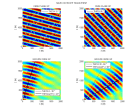
anisopro.m
To compute the QP-QSV reflection-transmission coefficients, the components of particle motion are written as a function of the polarization angle α for the QP waves and of the angle β = QSV polarization angle + π/2 for the QS waves (same as in the isotropic case). Snell's law still applies but it does not give explicitely the different incidence angles since velocities depend on these angles. The dispersion relation provides the angles θ(p) and η(p), or more generally kzP = ωqP(p) and kzS = ωqS(p), wich are imaginary for evanescent waves.
|
Snell's law : p = sinθ1/VQP1(θ1) = sinθ2/VQP2(θ2) = sinη1/VQS1(η1) = sinη2/VQS2(η2) ;
qP1(p) = (cosθ1/VQP1)(p) ; qP2(p) = (cosθ2/VQP2)(p) ; qS1(p) = (cosη1/VQS1)(p) ; qS2(p) = (cosη1/VQS2)(p) ; Dispersion relation : (ρ-c11p2-c44q2)(ρ-c44p2-c33q2)-((c13+c44)pq)2 = 0 Aq4+Bq2+C = 0 ; A = c33c44 ; B = -c33(ρ-c11p2)-c44(ρ-c44p2)-(c13+c44)2p2 ; C = (ρ-c11p2)(ρ-c44p2) ; Δ = (B2-4AC)½ qP = ((-B-Δ)/2A)½ ; qS = ((-B+Δ)/2A)½ ; Polarization : α = Arctan((c13+c44)pqP/(ρ-c11p2-c44(qP)2)) ; β = π/2+Arctan((c13+c44)pqS/(ρ-c11p2-c44(qS)2)) | ||||
| QP incident downgoing + reflected upgoing UI = (sinα1,cosα1) , URP = RP(sinα1,-cosα1) kzI = ωqP1(p) , kzRP = -ωqP1(p) | QSV reflected upgoing URS = RS(cosβ1,sinβ1) kzRS = -ωqS1(p) | QP transmitted downgoing UTP = TP(sinα2,cosα2) kzTP = ωqP2(p) | QSV transmitted downgoing UTS = TS(-cosβ2,sinβ2) kzTS = ωqS2(p) | |
| Ux = | sinα1(1+RP) | + cosβ1RS | = sinα2TP | -cosβ2TS |
| Uz = | cosα1(1-RP) | + sinβ1RS | = cosα2TP | + sinβ2TS |
| Σzz = | (c13sinα1p+c33cosα1qP1)(1+RP) | + (c13cosβ1p-c33sinβ1qS1)RS | = (d13sinα2p+d33cosα2qP2)TP | + (-d13cosβ2p+d33sinβ2qS2)TS |
| Σzx = | c44(sinα1qP1+cosα1p)(1-RP) | + c44(-cosβ1qS1+sinβ1p)RS | = d44(sinα2qP2+cosα2p)TP | + d44(-cosβ2qS2+sinβ2p)TS |
| écriture matricielle : AR = B ; R = [RP , RS , TP , TS]t ; B = [-sinα1 , -cosα1 , -(c13sinα1p+c33cosα1qP1) , c44(sinα1qP1+cosα1p)]t | ||||
| A | sinα1 | cosβ1 | -sinα2 | cosβ2 |
| -cosα1 | sinβ1 | -cosα2 | -sinβ2 | |
| (c13sinα1p+c33cosα1qP1) | (c13cosβ1p-c33sinβ1qS1) | - (d13sinα2p+d33cosα2qP2) | (d13cosβ2p-d33sinβ2qS2) | |
| c44(sinα1qP1+cosα1p) | c44(cosβ1qS1-sinβ1p) | d44(sinα2qP2+cosα2p) | d44(-cosβ2qS2+sinβ2p) | |
Here are the coefficients computed for an interface between a slow isotropic medium and a fast transverse isotropic medium in the case where a P wave is incident
in the isotropic medium :

anisopro.m
Winterstein D.F. and G. S. De, 2001, VTI documented
document the effect of transverse isotropy on S waves recorded in a 9-component vertical seismic profile.
Johnston, J. E. and Christensen, N. I. 1995, Seismic anisotropy of shales
measure phase and group velocities in shales.
Godfrey, N.J. ; Christensen, N. I. and Okaya, D.A. 2000,
Anisotropy of schists: Contribution of crustal anisotropy to active source seismic experiments and shear wave splitting observations.
|
displacement
equilibrium eq. | cinetic energy density (Jm-3) | elastic energy density (Jm-3) | power density Pt (Wm-2) | intensity I (Wm-2) |
|
u(x,t)
ρ∂2u/∂t2 = ∂σ/∂x |
wc = (ρ/2)(∂u/∂t)2
∂wc/∂t = (∂σ/∂x)(∂u/∂t) |
we = ∫σdε = (E/2)ε2
∂we/∂t = σ∂/∂x(∂u/∂t) |
∂(wc+we)/∂t = ∂/∂x(σ∂u/∂t)
Pt = -σ∂u/∂t | (1/T)∫0TPtdt |
| u(x,t) = Ucos(kx-ωt) | wc = (ρ/2)ω2U2sin2(kx-ωt) | we = (ρ/2)V2k2U2sin2(kx-ωt) | Pt = ρVω2U2sin2(kx-ωt) = V(wc+we) | (ρ/2)Vω2U2 |
|
u = gradφ(x,t)
ρ∂2u/∂t2 = -gradp |
wc = (ρ/2)(∂u/∂t)2
∂wc/∂t = -gradp.∂u/∂t |
we = (K/2)(divu)2
∂we/∂t = -pdiv∂u/∂t |
∫dx∂(wc+we)/∂t = -∫dxdiv(p∂u/∂t) = -∫(p∂u/∂t).dS
Pt = p∂u/∂t | (1/2)ℜ(p∂u*/∂t) |
| 2π/quality factor = energy dissipated per cycle / maximum elastic energy | cycle = λ | amplitude | displacement | complex velocity VQ = V(1-i/2Q) |
| 2π/Q = -(δw)cycle/wmax | π/Q = -(dU/dx)λ/U | U(x) = Ue-αx
α = π/Qλ = k/2Q = ω/2QV | u(x,t) = Ue-αxcos(kx-ωt) | u(x,t) = Ue-αxeiω(x/V-t) = Ueiω(x(1+i/2Q)/V-t)
u(x,t) = Ueiω(x/VQ-t) |
| linear viscoelasticity | energy dissipated per cycle | maximum elastic energy | qualty factor |
| σ = σmcos(ωt+χ)
ε = εmcosωt | (δw)cycle = ∫0Tσdε = πσmεmsinχ | wmax = ∫0T/4σdε ≈ -(1/2)σmεmcosχ | 1/Q = tanχ ≈ χ |
| viscoelastic model , elastic modulus E , viscosity η | complex wavenumber k+iα | weak attenuation , 1/Q << 1 | 1/Q < 1 , dispersion V(ω) = ω/k |
| E and η in parallel, relaxation time τ = η/E
σ = Eε+η∂ε/∂t = E(1-iωτ)ε = Mε M = E(1+ω2τ2)½e-iχ , 1/Q = tanχ = ωτ | ρ∂2u/∂t2 = E(1-i/Q)∂2u/∂x2
ρω2 = E(1-i/Q)(k+iα)2 , k02 = ρω2/E k02 = (1-i/Q)(k+iα)2 | k+iα = k0(1+i/2Q)
k = k0 , V = V0 = ω/k0 α = k0/(2Q) = ω2τ/(2V0) | k2+α2 = k02/(1+1/Q2)½ ≈ k02(1-1/2Q2)
k2-α2 = k02/(1+1/Q2) ≈ k02(1-1/Q2) V(ω) ≈ V0(1+3/(8Q2)) = V0(1+3ω2τ2/8) , α = k0/(2Q) |
| (E and η in parallel) in series with E' , σ = M''ε
1/M'' = 1/M+1/E' = 1/E(1-iωτ)+1/E' = (1/E+1/E'-iωτ/E')/(1-iωτ) 1/E'' = 1/E+1/E' , τ'' = τE''/E' , M'' = E''(1-iωτ)/(1-iωτ'') = ||M''||e-i(χ-χ'') 1/Q = tan(χ-χ'') = ω(τ-τ'')/(1+ω2ττ'') d(1/Q)/dω = 0 pour ωr = (ττ'')-½ and (1/Q)max = (τ-τ'')/2(ττ'')½ | ρω2 = M''(k+iα)2 , k''02 = ρω2/E''
k2+α2 = ρω2/||M''|| = k''02(1+ω2τ''2)½/(1+ω2τ2)½ k2-α2 = ρω2ℜ(1/M'') = k''02(1+ω2ττ'')/(1+ω2τ2) k2 = ω2/V(ω)2 = (k''02/2)((1+ω2τ''2)½/(1+ω2τ2)½+(1+ω2ττ'')/(1+ω2τ2)) | ||
| constant Q model (Kjartansson, 1979, JGR, 84, 4737)
M = M0(iω/ω0)2γ = M0(|ω/ω0|)2γeiπγsign(ω) 1/Q = tan(πγ) | ρω2 = M0(|ω/ω0|)2γeiπγsign(ω)(k+iα)2
k2+α2 = k02(|ω/ω0|)-2γ k2-α2 = k02(|ω/ω0|)-2γcos(πγ) | k = k0(|ω/ω0|)-γcos(πγ/2)
V(ω) = V0(|ω/ω0|)γ/cos(πγ/2) α = k0(|ω/ω0|)-γsin(πγ/2) = ktan(πγ/2) | dispersion pour 1/Q << 1
V(ω)/V0 ≈ (|ω/ω0|)1/πQ = eLog(|ω/ω0|)/πQ V(ω)/V0 ≈ 1+Log(|ω/ω0|)/πQ |
| Φ = ΩΦ/Ω = Ωf/Ω | ε = δΩ/Ω | ζ = (δΩΦ-δΩf)/Ω = Φ(δΩΦ/ΩΦ-δΩf/Ωf) = Φ(εΦ-εf) |
La théorie de la poroélasticité linéaire isotrope exprime ε and ζ comme une combinaison linéaire de σ and pf , la variation de pression de fluide dans les pores. La signification des coefficients de proportionnalité α (coefficient de Biot-Willis) and B (coefficient de Skempton) apparaît en considérant les cas d'une roche drainée (pression de fluide constante, incompressibilité K), non-drainée (contenu en fluide constant, incompressibilité Ksat) and d'une pression différentielle nulle (pressions de confinement and de fluide égales). Dans ce dernier cas, la déformation homogène est celle de la roche sans pore d'incompressibilité K0 and la déformation volumique εΦ des pores est égale à la déformation volumique ε de la roche : on obtient ainsi la relation de Gassmann entre Ksat, K0 , K , Kf (l'incompressibilité du fluide) and Φ. Candte relation permet de déterminer la vitesse de propagation des waves de compression dans les roches poreuses saturées en fluide à basse frequency (f < 100Hz).
| poroélasticité linéaire | ε = (1/K)(σ+αpf)
ζ = (α/K)(σ+pf/B) | incompressibilité | coef. poroélastiques |
| pf = 0 | ε = (1/K)σ | K | α = ζ/ε |
| ζ = 0 | ε = ((1-αB)/K))σ | K = (1-αB)Ksat | B = -pf/σ |
| σ = -pf | ε = ((1-α)/K))σ = σ/K0 | K = (1-α)K0 | . |
| εΦ = ζ/Φ+εf = ε
εf = -pf/Kf | (α/ΦK)(1-1/B)+1/Kf = 1/K0 | 1/B = 1-(ΦK/α)(1/K0-1/Kf) = α/(1-K/Ksat) | |
| relation de Gassmann |
1/Ksat = (1-α)/K+α/K(1-1/(1-(ΦK/α)(1/K0-1/Kf)))
1/Ksat = 1/K0+Φ/(ΦK/α+1/(1/Kf-1/K0)) 1/(1/Ksat-1/K0) = K/α+1/(Φ(1/Kf-1/K0)) = 1/(1/K-1/K0)+1/(Φ(1/Kf-1/K0)) | ||
| densité and vitesses | ρ = (1-Φ)ρ0+Φρf | VP2 = (Ksat+4μ/3)/ρ | VS2 = μ/ρ |
Wang Z., 2001, Fundamentals of seismic rock physics
montre comment la relation de Gassmann est utilisée dans l'étude sismique des réservoirs.
Smith, T.M., C. H. Sondergeld, and C. S. Rai, 2003,
Gassmann fluid substitutions: A tutorial
Chapman, N.R., J. F. Gandtrust, R. Walia, D. Hannay, G. D. Spence, W. T. Wood, and R.D. Hyndman , 2002, High-resolution, deep-towed, multichannel seismic survey of deep-sea gas hydrates off western Canada
Alternatively, one may consider one upgoing wave (sum of all upgoing waves in the layer) and one downgoing wave (sum of all downgoing waves in the layer). The upgoing and downgoing waves in 2 layers having a common interface are linked by continuity conditions. By using iteratively these conditions from the bottom to the top of the stratification, one gets the reflection-transmission coefficients on the stratification. By computing these coefficients for different frequencies, one gets the seismic trace in time by inverse Fourier transform. To take into account the free surface (R = 1), the upgoing reflected wave is sent back in the stratification. This is done iteratively to take into account multiple reflections on the free surface.
|
layer
Rinterface |
downgoing waves downgoing
Dj = Tj+1Dj+1eikzjhj-Rj+1Mje2ikzjhj Dj+1 = (Dje-ikzjhj+Rj+1Mjeikzjhj)/Tj+1 |
upgoing waves
Mj+1 = Rj+1Dj+1+(1-Rj+1)Mjeikzjhj Mj+1 = (Rj+1Dje-ikzjhj+Mjeikzjhj)/Tj+1 |
reflection coef. on stratification
Rh1..j = Mj+1/Dj+1 Rj+1 = (Rh1..je-ikzjhj-Rh1..j-1eikzjhj)/(e-ikzjhj-Rh1..j-1Rh1..jeikzjhj) |
transmission coef. on stratification
Th1..j = D0/Dj+1 |
|
layer 3
R3 | D3 = (e-ikz2h2+R3Rh1eikz2h2)D2/T3 | M3 = (R3e-ikz2h2+Rh1eikz2h2)D2/T3 |
Rh12 = M3/D3
R3 = (Rh12e-ikz2h2-Rh1eikz2h2)/(e-ikz2h2-Rh1Rh12eikz2h2) | Th12 = D0/D3 = Th1D2/D3 |
|
layer 2
R2 | D2 = (e-ikz1h1+R2R1eikz1h1)D1/T2 | M2 = (R2e-ikz1h1+R1eikz1h1)D1/T2 |
Rh1 = M2/D2
R2 = (Rh1e-ikz1h1-R1eikz1h1)/(e-ikz1h1-R1Rh1eikz1h1) | Th1 = D0/D2 = T1D1/D2 |
|
layer 1
R1 | D1 | M1 | R1 = M1/D1 | T1 = D0/D1 |
| 1/2 space | D0 | M0 = 0 |
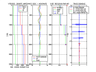
stratif.m | |
For P-SV waves, there are two upgoing and two downgoing waves in each layer (φ and ψy potentials)
|
downgoing P and SV waves
DPj = (TPPj+1DPj+1+TSPj+1DSj+1+RPPj+1MPjeikzPjhj+RSPj+1MSjeikzSjhj)eikzPjhj DSj = (TPSj+1DPj+1+TSSj+1DSj+1+RPSj+1MPjeikzPjhj+RSSj+1MSjeikzSjhj)eikzSjhj |
upgoings P and SV waves
MPj+1 = RPPj+1DPj+1+RSPj+1DSj+1+TPPj+1MPjeikzPjhj+TSPj+1MSjeikzSjhj MSj+1 = RPSj+1DPj+1+RSSj+1DSj+1+TPSj+1MPjeikzPjhj+TSSj+1MSjeikzSjhj | ||||
|
(TPPj+1TSSj+1-TPSj+1TSPj+1)DPj+1
(TSPj+1TPSj+1-TSSj+1TPPj+1)DSj+1 | TSSj+1e-ikzPjhj | -TSPj+1e-ikzSjhj | (TSPj+1RPSj+1-TSSj+1RPPj+1)eikzPjhj | (TSPj+1RSSj+1-TSSj+1RSPj+1)eikzSjhj) |
DPj
DSj MPj MSj |
| TPSj+1e-ikzPjhj | -TPPj+1e-ikzSjhj | (TPPj+1RPSj+1-TPSj+1RPPj+1)eikzPjhj | (TPPj+1RSSj+1-TPSj+1RSPj+1)eikzSjhj) | ||
|
MPj+1
MSj+1 | RPPj+1 | RSPj+1 | TPPj+1eikzPjhj | TSPj+1eikzSjhj |
DPj+1
DSj+1 MPj MSj |
| RPSj+1 | RSSj+1 | TPSj+1eikzPjhj | TSSj+1eikzSjhj | ||
|
1 (0)
0 (1) RPPh1.n (RSPh1.n) RPSh1.n (RSSh1.n) | DM(4,4) = ∏ transfert matrices in layers 1 à n |
1
0 RPP1 RPS1 |
0
1 RSP1 RSS1 |
DP1
DS1 | |
|
liquid-solid case
DPj = (TPPj+1DPj+1+RPPj+1MPjeikzPjhj+RSPj+1MSjeikzSjhj)eikzPjhj | MPj+1 = RPPj+1DPj+1+TPPj+1MPjeikzPjhj+TSPj+1MSjeikzSjhj | ||||
|
1
RPPeau.h1.n | DMliq-sol(2,4) | DM(4,4) |
1
0 RPP1 RPS1 |
0
1 RSP1 RSS1 |
DP1
DS1 |
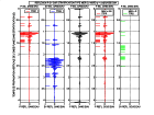
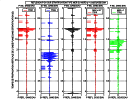
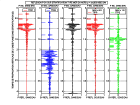
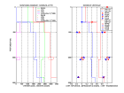
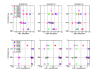
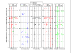
Exemples of potentials computed with a density-velocity model and incidence angles in water θ = 0°, 15° and 30° in cases corresponding to
land and marine reflection seismics (recording at the surface or at the bottom of the sea).
 -
-
 -
-
 -
-
 -
-
stratifpsv.m
Liu Y. and D. R. Schmitt, 2003, Amplitude and AVO responses of a single thin bed
Chapman, C. H., 2003, Yet another elastic plane-wave, layer-matrix algorithm
give a more elaborate program, that can be used for incidence angles larger than the critical value.
 -
-
 -
-
 -
-
 -
-

monitorpsv.m
| 1 path with (TeTs)m+1 | TS0 = TeeikzHTs∏(eikzHTeeikzHTs) = (1-Re2)m+1e(2m+1)ikzH |
transtrat.m |
| N1(2m+1) = 2m+1 paths with R2 | TS1 = TS0N1(2m+1)Re2e2ikzH | |
|
N2(2m+1) = N1(2m+1)+...+N1(1) paths with R4
N1(2m) paths with -R2,TeTs |
TS2 = TS0(N2(2m+1)Re4
-N1(2m)(1-Re2)Re2)e4ikzH | |
|
N3(2m+1) = N2(2m+1)+...+N2(1) paths with R6
2N2(2m+1)-2 paths with -R4,TeTs N1(2m-1) paths with R2,(TeTs)2 |
TS3 = TS0(N3(2m+1)Re6
-(2N2(2m+1)-2)(1-Re2)Re4 +N1(2m-1)(1-Re2)2Re2)e6ikzH | |
|
N4(2m+1) = N3(2m+1)+...+N3(1) paths with R8
3N3(2m+1)+N2(2m)-3 paths with -R6,TeTs 3N2(2m+1)-N2(2)-2 paths with R4,(TeTs)2 N1(2m-2) paths with -R2,(TeTs)3 |
TS4 = TS0(N4(2m+1)Re8
-(3N3(2m+1)+N2(2m)-3)(1-Re2)Re6 +(3N2(2m+1)-N2(2)-2)(1-Re2)2Re4 +N1(2m-2)(1-Re2)3Re2)e8ikzH |
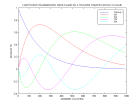
Les termes successifs des coefficients de transmission and reflection sont calculables sans avoir à dénombrer tous les trajands possibles en utilisant les récurrences reliant les waves upgoings Mj,n+1 and downgoings Dj,n+1 de part and d'autre de chaque interface j après n+1 reflection-transmissions à celles provenant des interfaces immédiatement au dessus Dj-1,n and en dessous Mj+1,n après n reflection-transmissions. On obtient ainsi les réponses impulsionelle and harmonique complètes de la stratification. Les réponses impulsionnelles en reflection and transmission sont caractérisées par des codas avec une amplitude décroissant exponentiellement. Les réponses harmoniques sont caractérisées par des pics de réflectivité (trous de transmissivité) pour H=(2n+1)λz/4 .
| initialisation | reflection-transmission on odd interface | reflection-transmission on even interface |
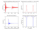
refltranstrat.m |
|
M1,1 = Re , D1,1 = Te
M2,2 = RsTeeikzH , D2,2 = TsTeeikzH |
R2n+1 = M1,2n+1 = TsM2,2neikzH
D1,2n+1 = RsM2,2neikzH M2j+1,2n+1 = (ReD2j,2n+TsM2j+2,2n)eikzH D2j+1,2n+1 = (TeD2j,2n+RsM2j+2,2n)eikzH |
M2j,2n+2 = (RsD2j-1,2n+1+TeM2j+1,2n+1)eikzH
D2j,2n+2 = (TsD2j-1,2n+1+ReM2j+1,2n+1)eikzH M2m+2,2n+2 = RsD2m+1,2n+1eikzH T2n+2 = D2m+2,2n+2 = TsD2m+1,2n+1eikzH |
Anstey N.A. and R. F. O'Doherty, 2002, Cycles, layers, and reflections: Part 1
explain the origin on reflections in stratified sedimentary basin as an effect of cyclical stratification.
Stewart, R.R., P. D. Huddleston, and T. K. Kan, 1984,
Seismic versus sonic velocities: A vertical seismic profiling study
explain the difference between local velocity measurements in wells and velocities measured from the surface as an effect of cyclical stratification.
| SH case | incident wave at top (a) | incident wave at bottom (b) | reversal (a) + propagation | reversal (b) + propagation | ||||
| propagation direction | ↓ | ↑ | ↓ | ↑ | ↓ | ↑ | ↓ | ↑ |
| top | 1 | Rh | 0 | th | Rh* | 1 = RhRh*+thTh* | th* | 0 = Rhth*+thrh* |
| bottom | Th | 0 | rh | 1 | 0 = ThRh*+rhTh* | Th* | 1 = Thth*+rhrh* | rh* |
Pour le cas d'une couche d'épaisseur H dans un milieu homogène, Re étant le coefficient de reflection SH sur l'interface à l'entrée de la couche, on vérifie :
| layer | incident wave at top (a) | incident wave at bottom (b) | reversal (a) + propagation | ||
| top | 1 | Rh = Re(1-e2ikzH)/(1-Re2e2ikzH) | 0 | th = Th | RhRh*+thTh* = (Re2(1-e2ikzH)(1-e-2ikzH)+ (1-Re2)2) /((1-Re2e2ikzH)(1-Re2e-2ikzH)) = 1 |
| bottom | Th = (1-Re2)eikzH/(1-Re2e2ikzH) | 0 | rh = Rh | 1 | ThRh*+rhTh* = Re(1-Re2)(eikzH(1-e-2ikzH)+e-ikzH(1-e2ikzH)) /((1-Re2e2ikzH)(1-Re2e-2ikzH)) = 0 |
Par ailleurs, les flux d'énergie entrant and sortant de la stratification doivent être égaux.
| SH impedance x cos(incidence) | incident wave at top | incident wave at bottom | ||
| energy flux | entering | outgoing | entering | outgoing |
| top : Ia = (ρVScosη)haut | Ia | IaRhRh* | 0 | Iathth* |
| bottom : Ib = (ρVScosη)bas | 0 | IbThTh* | Ib | Ibrhrh* |
| flux conservation | Ia(1-RhRh*) = IbThTh* | Ib(1-rhrh*) = Iathth* | ||
| transmission/reflection relations | thTh* = 1-RhRh* = 1-rhrh* = (Ib/Ia)ThTh* | th = (Ib/Ia)Th | RhRh* = rhrh* | |
Si la stratification est limitée par une surface libre, il y a reflection totale sur celle-ci. Pour une onde incidente downgoing, la réponse en reflection de la stratification est renvoyée vers le bas. L'autocorrélation de la réponse en transmission downgoing D dans le demi-espace sous la stratification est proportionnelle à la somme de l'onde incidente, de la réponse en reflection and de sa randournée temporelle. De même, pour une onde incidente upgoing, l'autocorrélation de la réponse en transmission upgoing M dans la couche sous la surface libre est proportionnelle à la somme de l'onde incidente, de la réponse en reflection and de sa randournée temporelle.
| incident wave | transmission + 1 reflection on free surface | autocorrelation | reflection + time reversal |
| downgoing in layer | D = Th(1+Rh) | DD* = ThTh*(1+Rh)(1+Rh)* = (Ia/Ib)Thth*(1+Rh)(1+Rh)* = (Ia/Ib)(1-RhRh*)(1+Rh)(1+Rh)* | DD* ≈ (Ia/Ib)(1+Rh+Rh*) |
| upgoing in half-space | M = th(1+Rh) | MM* = thth*(1+Rh)(1+Rh)* = (Ib/Ia)Thth*(1+Rh)(1+Rh)* = (Ib/Ia)(1-RhRh*)(1+Rh)(1+Rh)* | MM* ≈ (Ib/Ia)(1+Rh+Rh*) |
| incident+reflected harmonic wave on free surface z=0 | pressure = 0 on free surface
z = h(x) = Heikhx | wave = p0 + scattered wave | Ps<<P0
kz0H<<1 | harmonic wave scattered in θs direction |
| p0(x,z) = P0eikx0x(e-ikz0z-eikz0z)
p0(x,0) = 0 | p(x,h(x)) = 0 p(x,0)+h(x)∂p/∂z(x,0) ≈ 0 | p(x,z) = (p0+ps)(x,z) ps(x,0) = -h(x)∂(p0+ps)/∂z(x,0) | ps(x,0) ≈ -h(x)∂p0/∂z(x,0) ps(x,0) =Pseikxsx Ps = -2ikz0HP0 kxs = (kx0+kh) | ps(x,z) = Pseikxsxeikzsz
sinθs = sinθ0+Vkh/ω kzs = (ω2/V2-kxs2)½ |